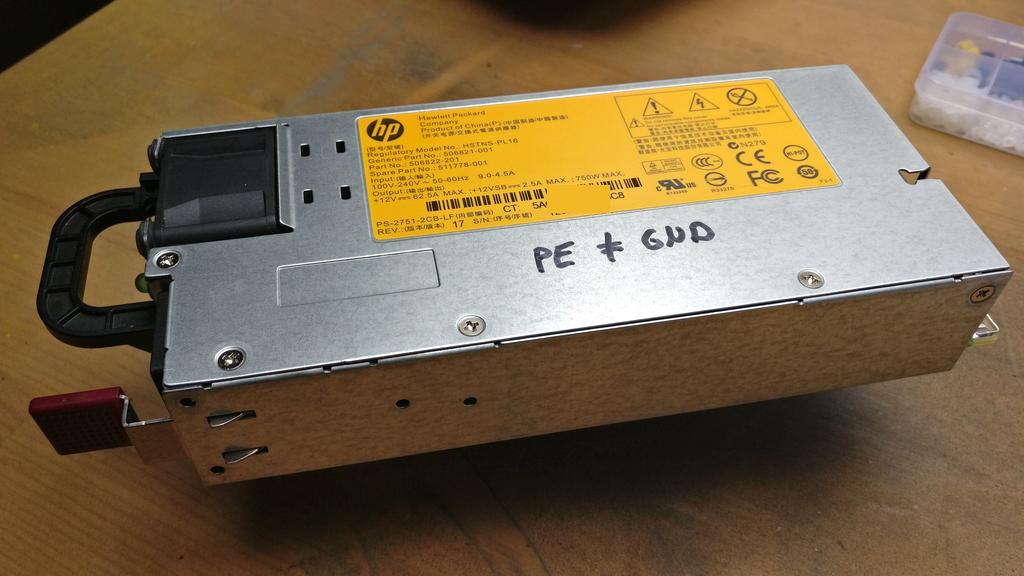
This article describes how to make a power supply with a so called floating ground from a regular server power supply. This is needed for example when connection multiple DC power sources in series to reach a higher voltage. To understand why this is necessary, please check out my other article about making a floating ground power supply.
Mains voltage is dangerous and can be lethal!
Always make sure to unplug the device when working on it!
Even when disconnected, the capacitor(s) of a DC power supply can store a high voltage/current for a significant amount of time. Always make sure to isolate or discharge these components first!
If you’re unsure or feel uncomfortable working on such devices — don’t do it!
Before connecting any power supplies in series, all added power supplies need to have a “floating ground”. This means, there is still a voltage of 12 V between GND and +12V (or whatever the voltage may be), but the GND output isn’t connected to the case/PE anymore. Only the first supply’s GND may be tied to earth/PE.
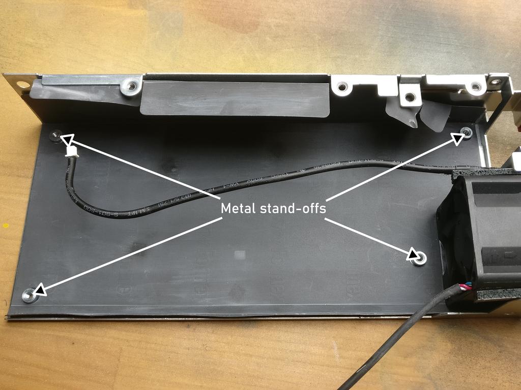
Server power supplies (and many other computer power supplies), in most cases, use one or more of their metal PCB standoffs, to connect to the metal casing and therefore the PE conductor (because it’s also connected to the case). This is done by simply putting an exposed GND pad (an exposed contact on the circuit board), where the standoff later touches the PCB. This connection needs to be undone.
Finding the connections
The best way to do this properly, is to remove the whole PCB of the power supply, disconnect it from the case, turn it around and measure between the pads (if any) at the screw holes. You may find, that all, only some or only one is connected to the GND plane of the PCB. Don’t just trust what others say, measure it yourself! Also note, that there is a difference between the DC GND and the AC “GND”/PE. The AC PE connector should always be connected to the primary (AC input) side of the power supply PCB (and therefore the case). Only the secondary (DC output) side needs to be isolated. There is usually a air gap on the PCB where primary and secondary sides meet.
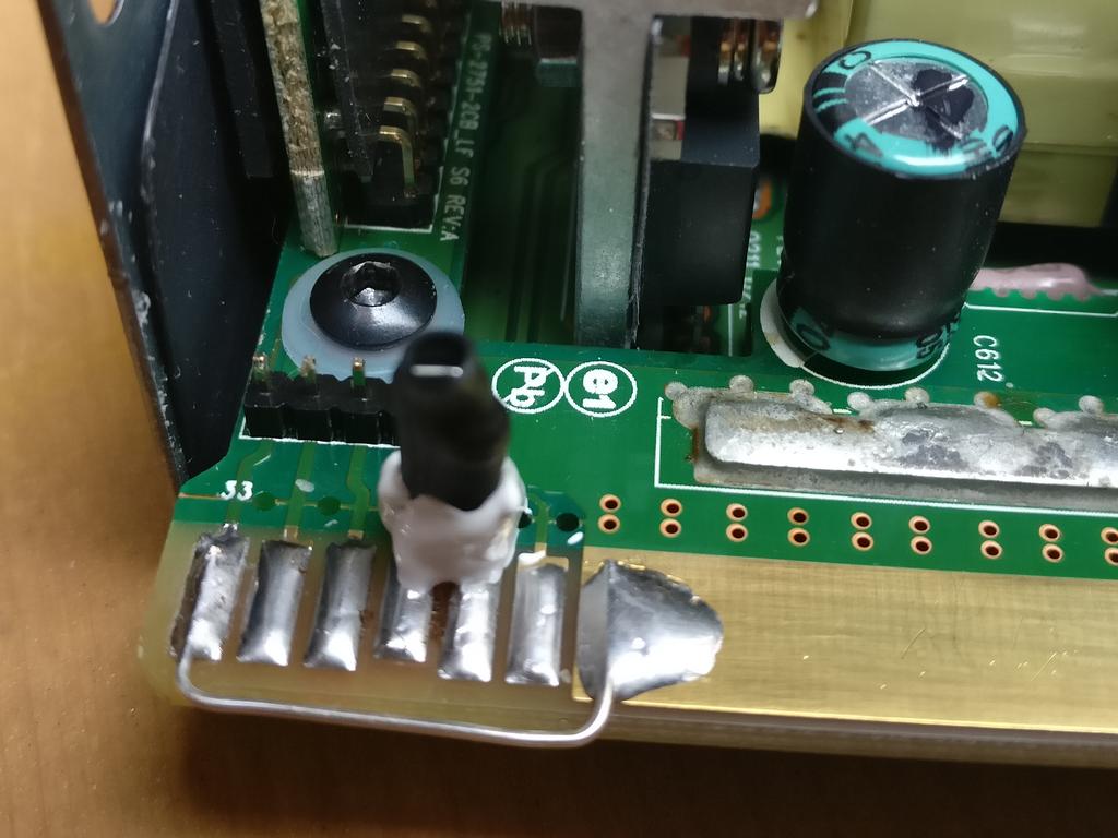
So basically every screw hole with a conductive pad around it, that is connected to the outputs GND (see picture below on the right side) needs to be isolated. If you don’t understand why, please check out the drawings in my other article.
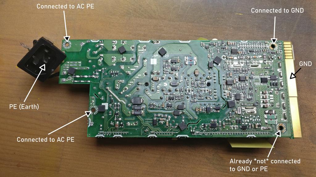
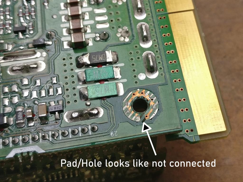
Only isolate screws that actually need to be isolated! Don’t just replace all stand-offs with nylon spacers/washers and nylon screws! The connection to PE on the primary side of the PCB (see above picture on the left) is actually needed for filtering purposes! Always reconnect the green/yellow PE conductor near the IEC connector! The case needs to be connected to PE, for its protective function to work. Also there may be some pads around some of the screw holes, that are not connected rest of the circuitry at all (even if they have a tinned copper pad around them).
In this example (see pictures), only one stand-off needed to be isolated, because the two on the left are only connected to PE and “AC GND” (primary side) anyway and the one on the bottom right wasn’t connected to anything at all (except the case, when put together again). The one on the top right is connected to DC GND (large pad on the right) and will be connected to Case/PE after reassembly — therefore this one really needed to be isolated!
Isolating the connection
There are multiple ways to isolate the PCB from the metal stand-off:
- Drill out the whole stand-off and use (a bigger) nylon stand-off and screw. Clean out the metal chippings after drilling!
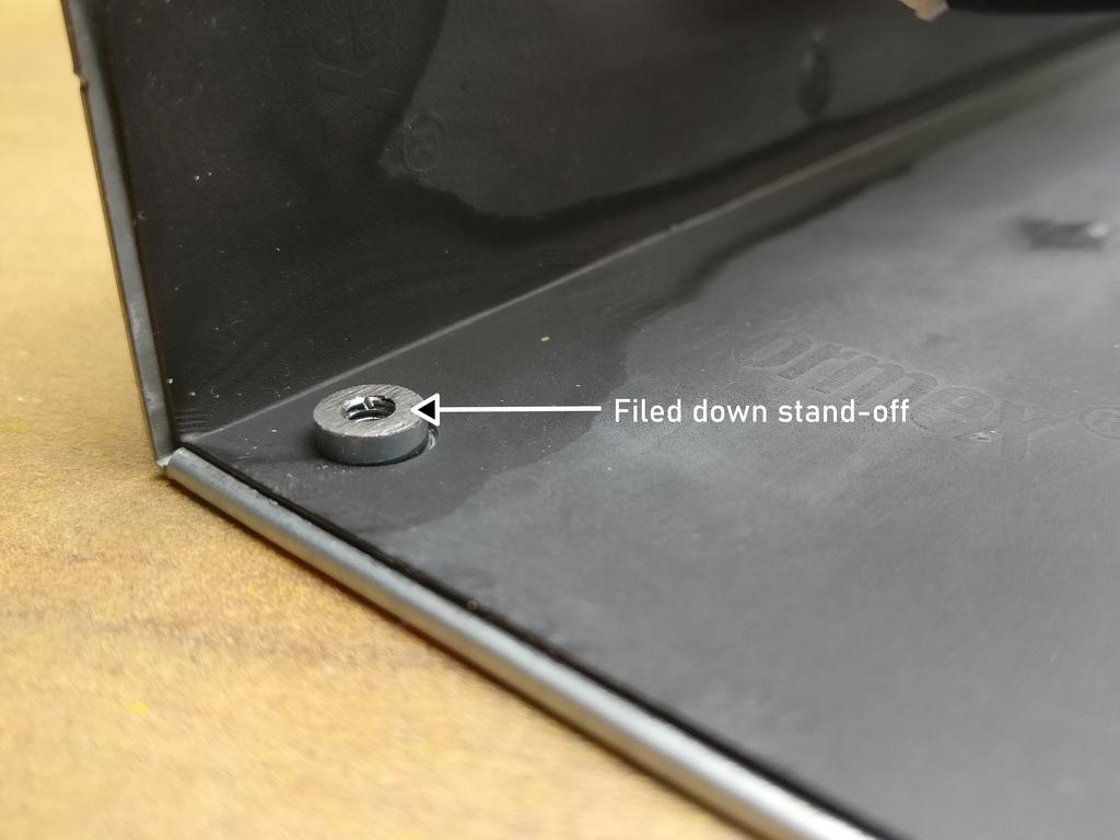
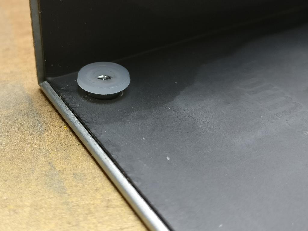
- File down the metal part and use a nylon washer and a nylon screw. Clean the metal dust carefully after, since it’s conductive!
- Use a shoulder or insulation washer(s) to isolate the hole from the metal screw. These washers are specially made for this. This is the cleanest way in my personal opinion. But you need some that fit correctly.
- Use two nylon washers (top/bottom of PCB) and a metal screw, but only, if the insides of the hole on the PCB aren’t conductive and there’s a little space between the pad on the surface at the edge of the hole itself. Be careful with this one and inspect the hole with a continuity tester to make sure, the screw won’t touch any conductive parts. If unsure, use a nylon screw.
Testing the device
After carefully putting everything back together again (make sure to put back the black insulation foil and other insulation tape, like it was before) the following measurements should be made:
- Continuity between center PE pin on the IEC connector and the case
- No continuity between the case and the GND (DC negative) pin.
- Infinite resistance between GND and PE (not even Megaohms!).
- Turned on: 12 V (or a little bit more) voltage between GND and +12V.
- Turned on: 0 V voltage between case and +12V.

1 Reply to “Make a floating ground 12 V server power supply”