Server power supplies, like the HP DPS-750RB, are available for a low price, especially if they have been used before. This makes them ideal for powering chargers that allow for or even require a DC input voltage.
The downside is, that they only produce 12 V output voltage. Most chargers claim to be able to charge at high power, but often forget to mention, that these maximum values are only reachable at higher DC voltages. So at a certain point, the voltage needs to be increased to transfer more power, since the current is already maxed out at the given voltage.
Mains voltage is dangerous and can be lethal!
Always make sure to unplug the device when working on it!
Even when disconnected, the capacitor(s) of a DC power supply can store a high voltage/current for a significant amount of time. Always make sure to isolate or discharge these components first!
If you’re unsure or feel uncomfortable working on such devices — don’t do it!
Combining two or more devices
Under certain conditions, it is possible to combine multiple DC voltage sources. If the output of these power supplies is connected in series, these voltages will add up. This way, a 24 V (or more) power supply can be built, by combining two (or more) 12 V supplies.
The initially mentioned 12V server power supplies have their negative pole (also called GND or sometimes RTN) and the AC (mains) PE (protective earth, sometimes also called earth grounding or just earth) connected together. PE is usually also connected to the metal casing of the device, which is an actual safety feature, that makes sure, the case can never be live, if damage or failure occurs.
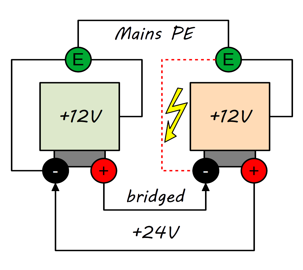
If another DC power supply is connected in series, the positive pole of the first supply will basically be shorted out. Why? Because the GND of the second one is also connected to the same earth wire (PE) and therefore also connected to the GND pole of the first power supply. Beste case scenario: The device will shut itself down. Worst case: Explosions. I’m not kidding!
Measuring and modifying the devices
You can easily test the actual configuration of a power supply, by using a continuity tester or a Ohm-meter and measure between “GND” and the metal casing of the device and/or the middle pin of the unplugged AC terminal on the power supply. If nothing has been altered yet, both should be connected together. If not, something is probably wrong.
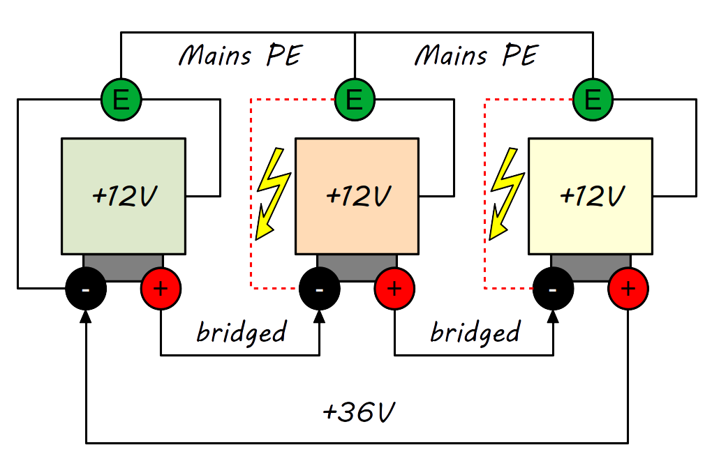
Before connecting anything in series, all added power supplies need to have a “floating ground”. This means, there is still a voltage of 12 V between GND and +12V, but the GND output isn’t connected to the case/PE anymore. Only the first supply’s GND may be tied to earth/PE.
How to correctly isolate the ground from PE and metal case, is described in detail in my other article. This modification is essential if you are planning on running multiple supplies in series!
Putting things together
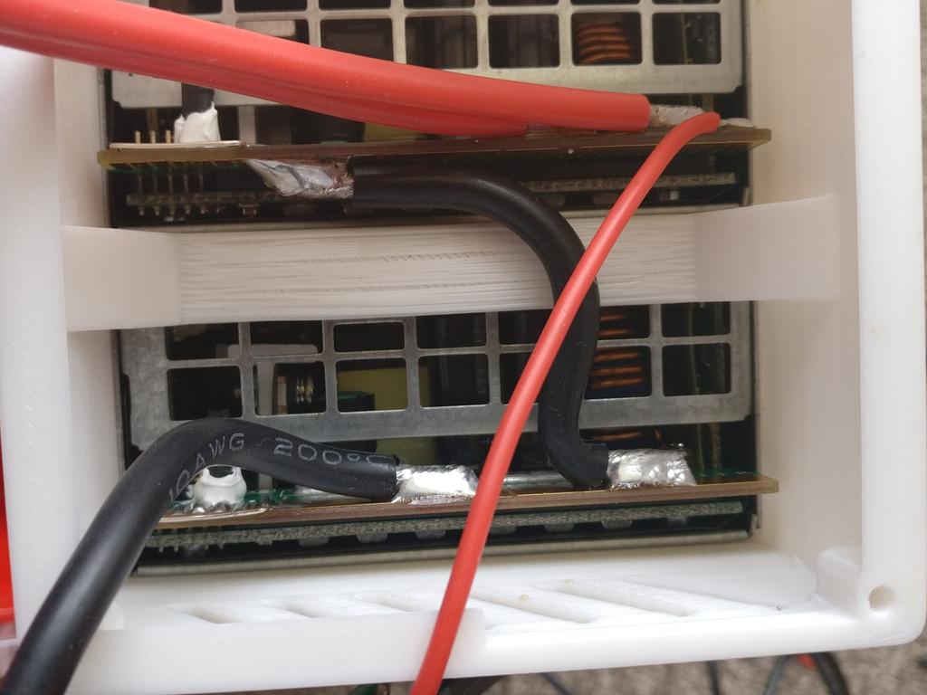
The rest of the setup is quite easy! To connect the devices, the positive pole of the first power supply is connected to the negative pole to the second one. Since all the current will pass through this connection, an adequate conductor diameter should be used and soldered properly to the pads of the power supplies.
The negative pole of the combined supplies will be the negative pole of the first device in the chain, while the positive pole of the combined supplies will be the positive pole of the last device in the chain (like shown in the images above).
This is basically the same thing as a Li-Po battery pack with multiple cells: The large connector, that carries the whole current, is connected to the first and the last cell, while the smaller balancing leads are connected in between the cells to measure their voltages.
Before powering on the devices, I recommend measuring one last time for continuity and resistance, like described in my other article.
The voltage doubles but the current does not
Always understand and remember what you are actually doing: Putting two battery cells of the same type in series, doubles their voltage, but the current, they can deliver, stays the same. The same is true for two DC power supplies. The total power (P) the combined batteries can deliver is measured in Watts (W).
This is just an example with made up values:
P=U \cdot I
P=1.5\,V \cdot 2\,A = 3\,W
The same for a power supply with the actual values:
P=12\,V \cdot 60\,A=720\,W
This is the power of one cell (first example) and one power supply (second example). If you add up multiple cells or power supplies (same type) in series, the power value in Watts also multiplies.
So, how much amps can your new combined power supply deliver?
The voltage is known (24 V), the total power is known, too (720 W * 2 = 1440 W):
I= \frac{P}{U}I=\frac{1440\,W}{24\,V}=60\,ASo basically, the power doubles and the voltage doubles, but the current stays the same.
Just FIY, if you put two power supplies in parallel, the power and the current doubles, while the voltage stays the same:
I=\frac{1440\,W}{12\,V}=120\,A
1 Reply to “Make a 24 V power supply from two 12 V supplies”