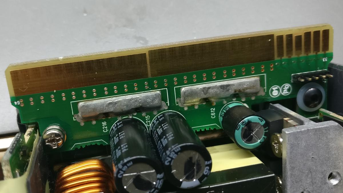
There are many tutorials and how-tos on the web, that use a resistor or wire to connect two pads on the top of the rear edge, to turn on the power supply. I found this a little bit odd, since regularly, one needs to pull a certain pin to ground (GND), to turn on the power supply, like it is the case with ATX power supplies.
So why this resistor? Some recommend 100 Ohm, others up to 1000 Ohm, some say to just connect them with a wire. For my device, only lower values and a simple wire would work.
I searched the web a while and found that there are others who have asked themselves the same question. I also found a interesting datasheet (PDF) for another, third party power supply, which had a lot of useful information on the “Common Slot” connection used for this (and many other) device(s).
Mains voltage is dangerous and can be lethal!
Always make sure to unplug the device when working on it!
Even when disconnected, the capacitor(s) of a DC power supply can store a high voltage/current for a significant amount of time. Always make sure to isolate or discharge these components first!
If you’re unsure or feel uncomfortable working on such devices — don’t do it!
Theory
In fact, there are two steps needed to turn on the power supply:
- Pull up the PRESENT pin #36 to 3.3 or 12 V using a resistor.
- Pull down the PSON pin #33 to GND (the above mentioned datasheet calls it “RTN”).
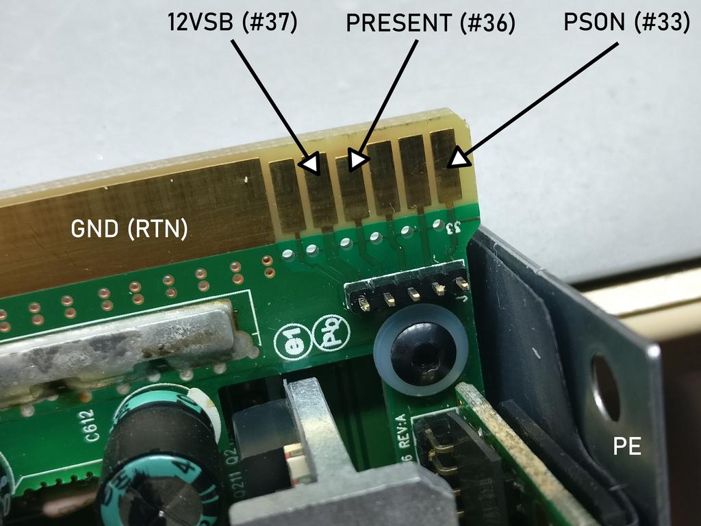
This is why only pulling down PSON didn’t work for me: PRESENT needs to be pulled up first (or at the same time). This basically tells the power supply it is now connected to a system (like it would be, when pushed into the slot it was designed for).
The single resistor is basically some kind of hardware hack, that seems, using the right resistance value, does these two things with only one connection. I don’t think this has a real downside, especially since most people do this and seem to have no issues with it. But I’m not 100% sure and also was interested in doing it the “right” way.
Practice
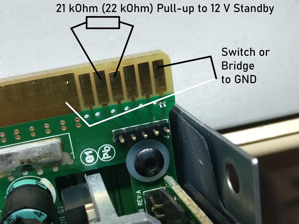
The “right” way seems to be to solder a 21 kOhm resistor from pin #36 (PRESENT) to the 12 V standby voltage (pin #37, 12VSB). I used a 22 kOhm resistor, since I didn’t have that value and it worked fine for me.
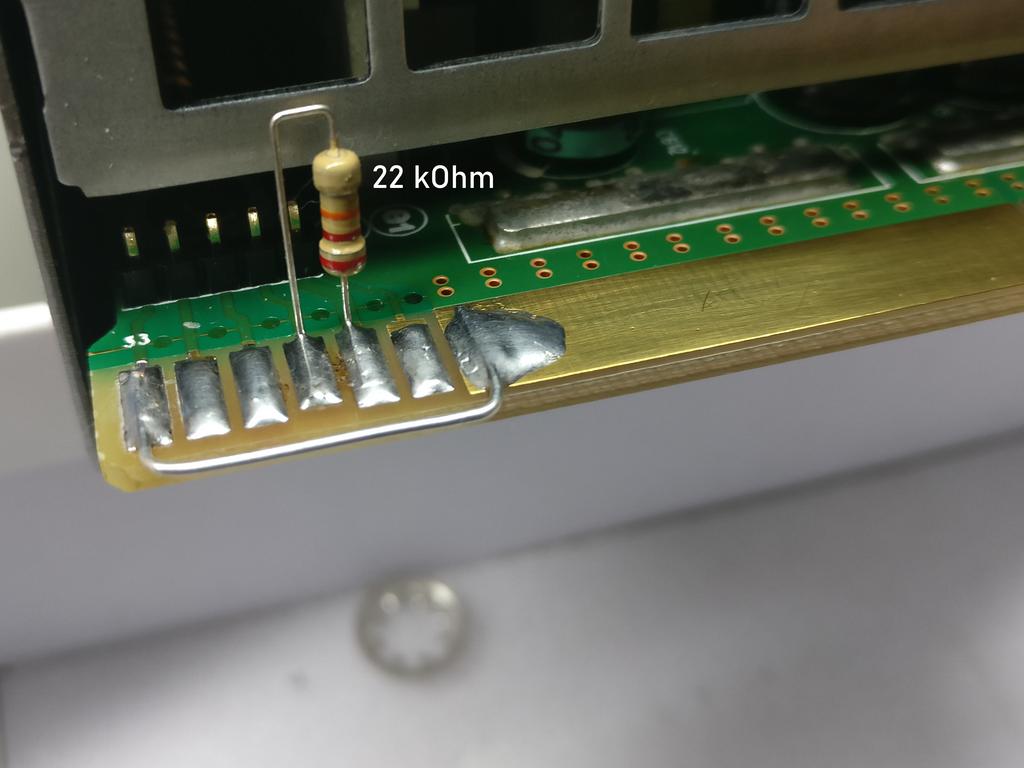
After that, connecting pin #33 (PSON) to GND/RTN (big pad) did in fact turn on the power supply for me. Of course, this can also be done by using a switch or a transistor. If connected permanently, the device will turn on as soon as DC power is connected and/or switched on.

By the way: It doesn’t matter if the device is in stock configuration or a “floating mod” has been applied to it (to connect multiple ones in series). In every case, each power supply needs to be turned on separately.
Connecting status LEDs
While we’re at it, it may be a good idea, to connect one or two LEDs, with a resistor, to indicate the state the power supply is in. In my opinion, the best solution, is to use the +12VSB (standby) and the actual +12V output for this. The standby voltage is available, as soon as the device is connected to a live mains socket. The +12V will obviously available, when the power supply is actually turned on. There is already a LED on the backside, but it’s pretty dim and you may want something brighter or on the other side of the device. For a regular 5 mm LED a 1 kOhm resistor should be fine. To be sure, individually calculate the resistance value.
i don’t understand, everybody else just bridges pin 33 and 36 together and it works, why is your way necessary if everybody else does it the easier way and it works? please explain
I don’t think it is necessary. The simple way is probably perfectly fine, especially since most people do it that way and do not have problems.
I was just curious to understand what exactly happens when the device gets plugged into a server rack.
CF, I found this explanation from a guy who designed systems that used high output power supplies. Not sure if you saw it already but here it is http://colintd.blogspot.com/2016/10/hacking-hp-common-slot-power-supplies.html?m=1
In my testing, a 22K resistor between pin 36 & 12V Standby power (pin 37) is enough to make the PSU think it is inserted into a slot. With the clamp action of the input, this gives around 500uA of current.
33 = Enable#
With the Present pin biased from 12VSB, pulling pin 33 directly to ground causes the main 12V output to enable. Looking at the current, open voltage and operation point, it looks like the pin is pulled up to the PSU internal 3V3 bus via a 10K resistor, and is monitored via a standard CMOS Schmitt trigger input gate.
I’ve not yet tried controlling the PSU over the PMBus, but PSU of this type can typically be enabled either via the Enable# pin, or via software control.
This splitting of 33 & 36, into a pulled up / clamped “present” signal, and a simple pull to ground “enable#” signal (which can also be driven over I2C) is much more consistent with other PSU I have worked with.
Given this understanding, you can see why the resistor between 33 & 36 works, because you are using the pull up on the Enable# input to bias the Present signal, and that load is in turn pulling Enable# low enough to operate.re is a fairly tight range of viable
However, in my own supply I will simply be going with a fixed 22K resistor from Present to 12VSB, and a separate switch between Gnd and Enable#, as that leaves the possibility of software control over the PMBus.
So froh und sehr dankbar für die Info.
Ein schöne PS is brauchbar,
Danke
So for the simple hack modification. A 300-400 ohm resistor is all that is needed? I’m reading online using a resistor anywhere between 300-1000 ohms, but why the range in ohms? (Sorry I am very new to this)
If I was to wire an LED push button switch for switching the unit on and I wanted the LED light to come on when the 12V+ came on would I need to do anything to limit the amps it saw?
Also, I have tried to put the led switch on the GND to Enable and it doesn’t seem to work. But when I hard wire the bridge between them it does work.
Most posts I find on the Internet have focus on increasing the output voltage to 13,8V, which is also the most interesting part of the PSU. But…If you do this mod the Over Voltage Protection (OVP) is shutting down the PSU in most cases. Unfortunately no one has come up with a good solution for the 460W and the 750W versions. As HAM-radio Amateur I would like to use the PSU for my treansceivers, but the OVP is killing the joy. Has anyone already found a good and working solution? If I could increase the OVP to 14,5 or even 15V the PSU should stay ON.
I have the same PSU, and I wanted to turn it on with a single grounding input and this works great for that. Only drawback is connecting the 22k resistor to the PRESENCE pin keeps the fan running at all times, even when off. It’s low speed so not loud, but kind of a drawback. Have you noticed that on yours?
Anyone have any information about using these to load share? I have a Ghetto Ghettoblaster Blaster project that will eat about 550W so I want to parallel two of these 750RBs to keep the fans from kicking on. I’ve only ever ran them one power supply to one amp, but wondering about bussing them in parallel then connecting all 5 amps (yeah) to the power bus for easier wiring and common grounded signaling. Any help would be greatly appreciated!