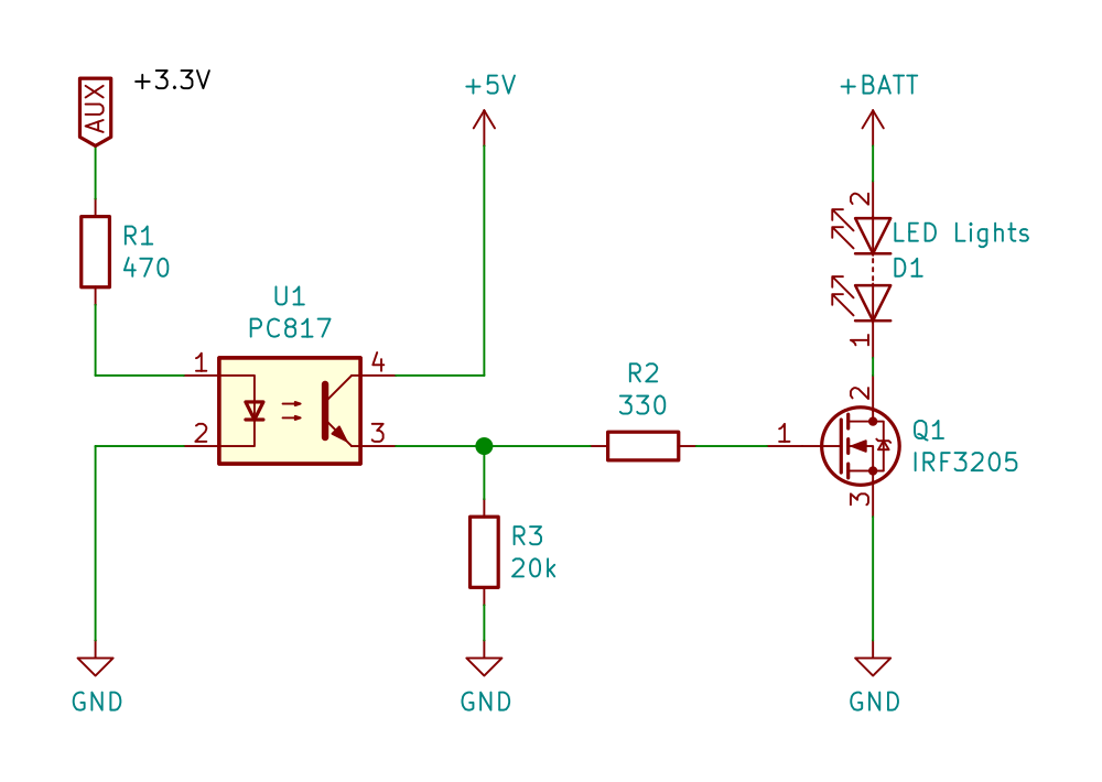
The Pixhawk flight controller, using the ArduPilot Copter firmware, allows for switching one or more AUX pins as GPIO pins from low to high (or vice versa) using the provided “Relay” function. Unfortunately the STM32 MCU of the Pixhawk uses a 3.3 V logic voltage on the white/yellow signal wire, which means that most regular MOSFETS won’t switch fully on because the gate voltage isn’t high enough. It is possible to use so called “Logic Level” MOSFETS, which allow for a lower gate voltage (also called “Vgs” in the datasheets). Since I hadn’t any of those available, I used an opto-coupler to switch the gate of the MOSFET with 5 V instead of 3.3 V.

The circuit is quite simple: The opto-coupler is switched on by the 3.3 V signal from the connected AUX port. The 470 Ohm resistor limits the current of the internal LED of the opto-coupler to about 5 mA. Different types of couplers may need more current or work with even less. I set this circuit up on a breadboard first and simply tested what worked and what did not. I recommend to do the same.
When the opto-coupler becomes conductive, the gate of the N-Channel MOSFET opens. It will not receive the full voltage (5 V), because of the semiconductor in between, but it still should be enough to allow all the needed current flowing from the drain (connected to LEDs cathode(s)) to the source (GND). The 330 Ohm resistor isn’t necessary, but makes sure that the current is limited for all connected devices. I added it last, when the rest of the circuit already worked fine. I recommend to do the same. The 20k resistor is a pull-down resistor to make sure the MOSFET switches off instantly, when the opto-coupler shuts off.
Make sure to select a power source that can deliver enough current for your LEDs! I’ve used a 5 V / 2 A integrated, linear BEC for a load of about 0.7 A and it’s already getting quite warm.
You may need to split up the connected leads or solder two cables to the board to get the 5 V from a BEC, while getting the signal from the FC. For loads above 0.5 A a switch mode regulator (switching BEC) is recommended (= higher efficiency and therefore less heat).
The above circuit should also work with higher LED supply voltages, like 9 V or 12 V, too. But make sure, that the “Gate-to-Source Voltage”, shown in the MOSFET’s datasheet, is never exceeded. In most cases the better approach would be to separate both lines and use 5 V only to switch the gate (see slightly altered circuit below).
Example build
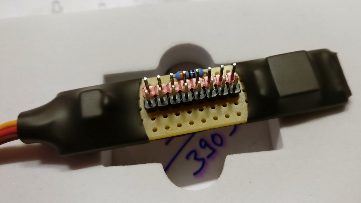
For this, I used a simple perfboard, some headers and put some 2-pin-plugs on the different lines coming from the navigation lights/arms of my drone. Please ignore the ceramic capacitor ;).

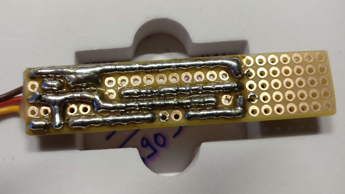
I used a perfboard for the circuit. The headers in the middle will be switched. Backside of the perfboard. 
Insulated backside. Insulated switch using some tape and heatshrink tubing. 
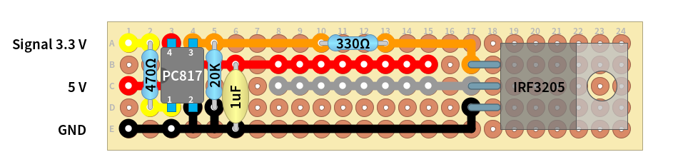
Perfboard layout (created with DIYLC)


Configuring AUX ports of the Pixhawk
The Pixhawk flight controller comes with six so called auxiliar (“AUX”) ports AUX1 to AUX6, which are assigned to the MCU pins #50 to #55. They can be configured for PWM or GPIO output.
Per default four of those ports (AUX1 to AUX4) are configured to output PWM signals, just like the main output channels. Only the last two of them (AUX5 and AUX6) are already configured to act as GPIO pin, or, more specifically, as a relay.
There are six of those virtual RELAY_PINn “objects” that basically map a selected RC channel to a selected AUX pin. For example, the RC channel #10 may point to RELAY_PIN2, which in return, points to AUX5.
You can test if it works, by simply measuring the voltage on the AUX pin, which should be 3.3 V in the enabled and about 0 V in the disabled state.
If you want to use AUX1, AUX2, AUX3 and/or AUX4 for a switch/relay, then you need to also change the BRD_PWM_COUNT parameter. Only pins that are not assigned as PWM output by this parameter, can be used as GPIO pins. This can be quite frustrating to set up right, since it’s possible to set the other parameters just fine, but they are still ignored as long as this option “overrides” the other ones.