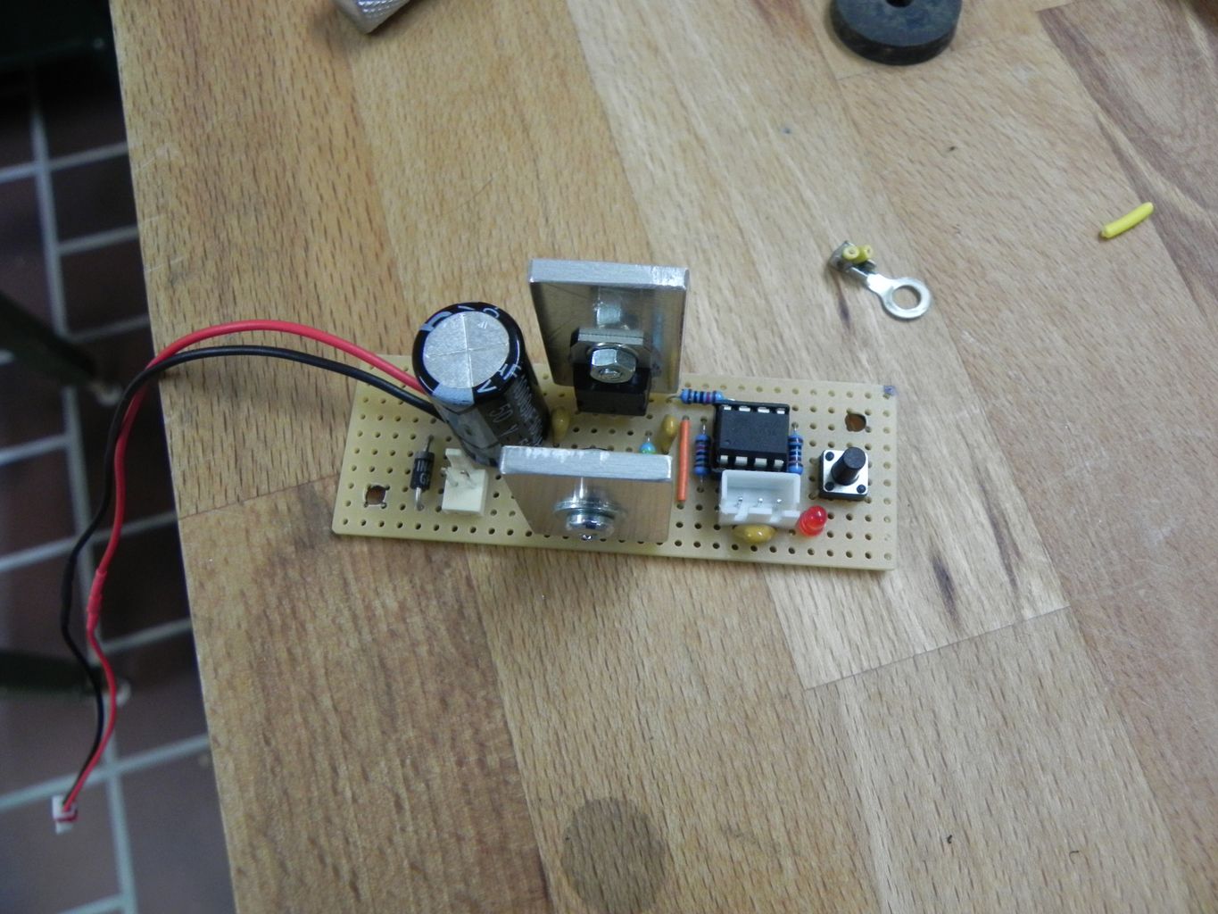
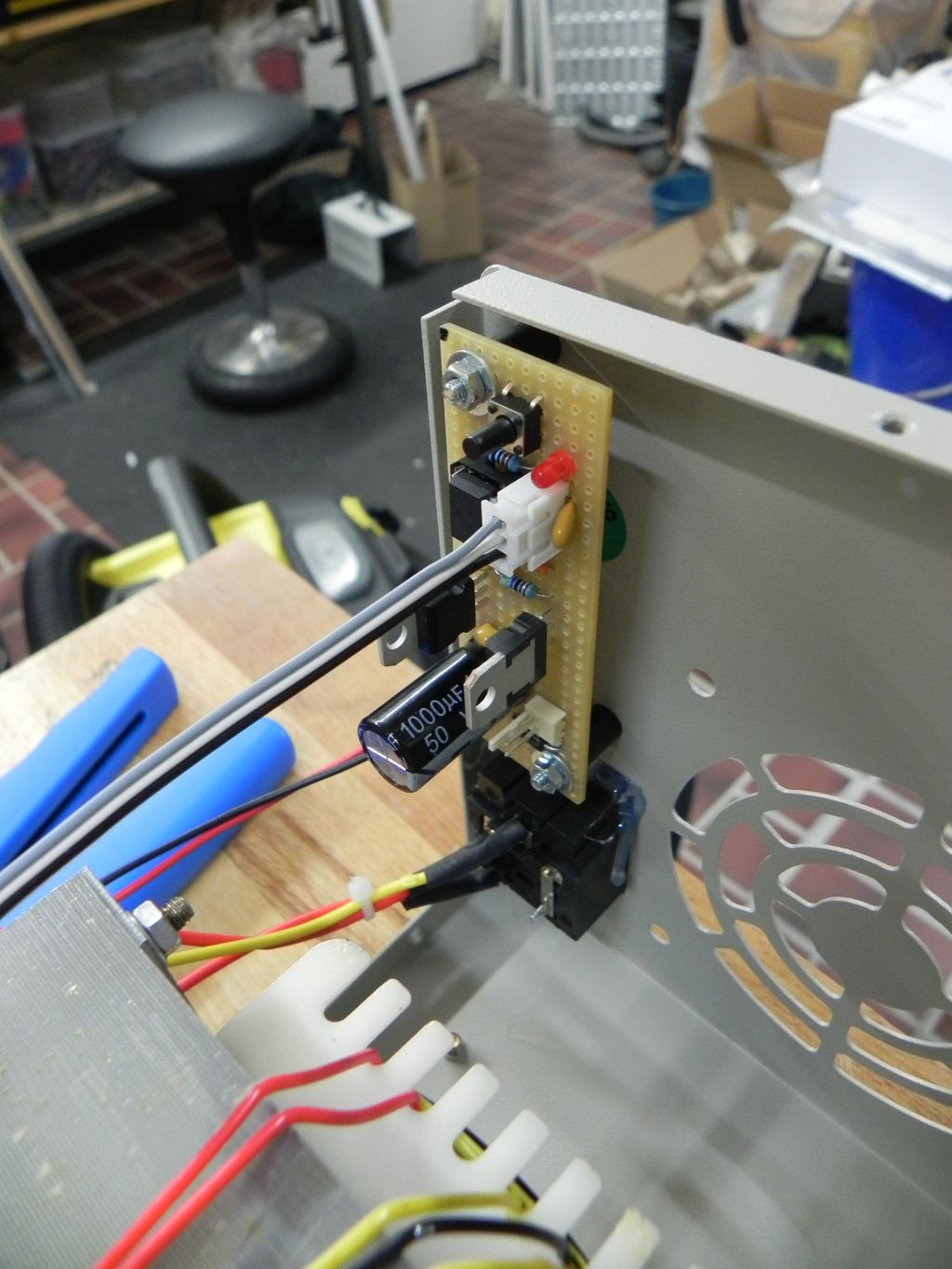
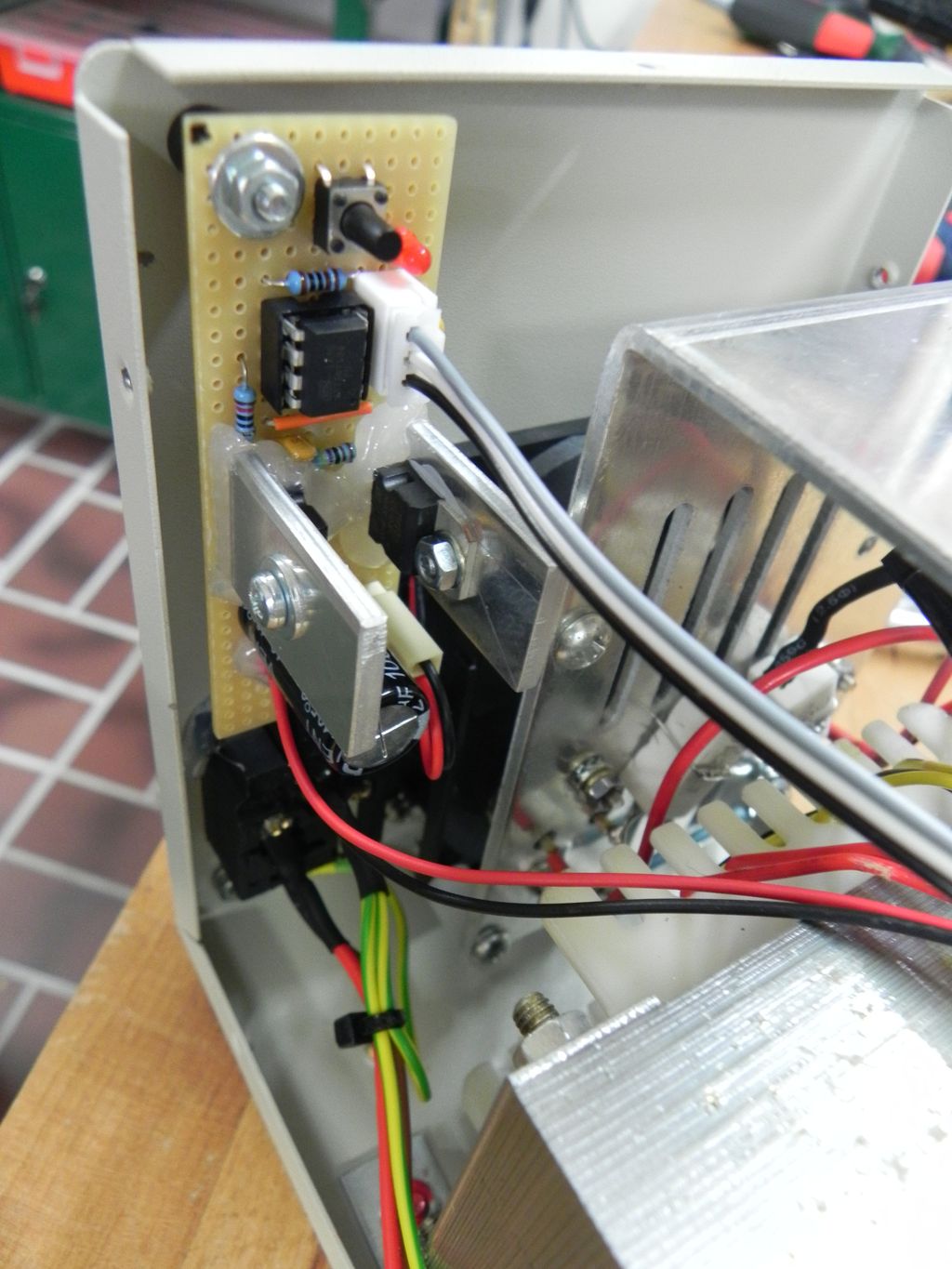
Like for the Lavolta power supply, I wanted to build a simple fan-controller circuit. Actually, I built this one first, and unlike the other one, which used the ATtiny85, I decided to build this one with a ATtiny13a. Because of this, the library for the DS18b20 digital sensor was too big to fit into the memory of the ATtiny13a. So I decided to use a TMP36 analog temperature sensor, since the controller already has a 10 Bit ADC and there is no need for another library.
This bench power supply actually came with a simple but working fan “controller”: The manufacturer ships these devices with a temperature switch, that turns the fan on, when it reaches a certain temperature (and off, if it drops below). There is nothing wrong with that! Still, I decided to go for the more complicated solution, since the switch can only turn the fan fully on or completely off, there is no in-between.

The basic setup is very simple: The micro-controller directly controls the base of a TIP120 Darlington transistor, which switches the 24 V power for the fan (using PWM). I know that a MOSFET would have been more efficient, but since the fan runs with 24 V, the voltage drop doesn’t matter that much. The LM7805 voltage regulator powers the micro-controller and the sensor (24 V to 5 V DC). Because the fan is a 24 V type, there was no need to use a buck converter or linear regulator.


Below you’ll find the source code written using avr-libc and avr-gcc for compiling it.
#ifndef __AVR_ATtiny13A__
#define __AVR_ATtiny13A__
#endif

#include <avr/io.h>
#include <avr/interrupt.h>

#define P_LED PB0
#define PORT_LED PORTB0
#define DD_LED DDB0

#define P_FANPWM PB1
#define DD_FANPWM DDB1

#define P_BUTTON PB2
#define PORT_BUTTON PORTB2
#define PIN_BUTTON PINB2

#define P_TMP36 PB4
#define ADC_TMP36 ADC2

/*
 * Pin 1 - Reset
 * Pin 2 - N/A
 * Pin 3 - [ADC2] TMP36 Sensor
 * Pin 4 - GND
 * Pin 5 - [PB0] LED
 * Pin 6 - [OC0B] PWM Lüfter
 * Pin 7 - [PB2] Taster
 * Pin 8 - VCC
*/

const uint8_t PWM_BOTTOM = 0;
const uint8_t PWM_TOP = 47;  // 48 Werte/Stufen (0-47)
const uint8_t FAN_MINIMUM = 10;  // Achtung: Lüfter läuft erst bei 7 an!
const int8_t TEMPERATURE_OFFSET = 0;  // Ausgleichwert für Temperatur
const uint8_t VREF = 5;

uint16_t volatile to_counter;  // Zähler für Timer-Overflows
uint8_t seconds_counter;

uint16_t volatile adc_raw;  // Letzer gemessener ADC-Wert

int8_t temperature_1s_ago;
int8_t temperature_1m_ago;


// Timer Overflow Interrupt ISR
// Aufruf der ISR setzt das TOV0 Flag im TIFR Register zurück.
ISR(TIM0_OVF_vect) {
  to_counter++;
}

// ADC Conversion Complete Interrupt ISR
// Aufruf der ISR setzt das ADIF Flag im ADCSRA Register zurück.
ISR(ADC_vect) {
  adc_raw = ADC;
  // Nächste Messung startet automatisch (Free Running Mode)
}

void setupTimer0(void) {
  // Register TCCR0A/B initialisieren
  // Fast-PWM Modus wählen (TOP = OCR0A)
  // OCR0B entspricht Duty-Cycle
  TCCR0A |= (1 << COM0B1) | (0 << COM0B0) | (1 << WGM01) | (1 << WGM00);

  // Counter initialisieren bzw. festlegen
  OCR0A = PWM_TOP;
  OCR0B = PWM_BOTTOM;  // Duty-Cycle

  // Prescaler auf 8 setzen
  // Formel für Fast-PWM-Frequenz: F_CPU / (Prescaler * 256)
  // 9,6 MHz: 9.600.000 / (8 * 48) = 25.000 Hz --> 25 kHz
  TCCR0B |= (1 << WGM02) | (0 << CS02) | (1 << CS01) | (0 << CS00);

  // Timer Overflow Interrupt einschalten
  // Erhöht Zählervariable
  TIMSK0 |= (1 << TOIE0);
}

void setupADC(void) {
  // ADC Multiplexer Selection Register
  // REFS0: VCC als Referenzspannung (Standard).
  // ADLAR: Left adjust ausschalten (siehe unten!)
  // MUX[1:0]: ADC2 (PB4, Pin 3) als analogen Eingang festlegen.
  ADMUX |= (0 << REFS0) | (0 << ADLAR) | (1 << MUX1) | (0 << MUX0);

  // Digitalen Input für analogen Pin abschalten
  DIDR0 |= (1 << ADC2D);

  // ADC Control and Status Register A
  // ADEN: ADC einschalten
  // ADSC: Einzelne Messung starten
  // ADIE: ADC Conversion Complete Interrupt einschalten
  // ADPS[2:0]: ADC Prescaler auf 64 (Ziel: zwischen 50 und 200 kHz)
  // 9,6 MHz: 9.600.000 Hz / 64 = 150.000 Hz --> 150 kHz
  ADCSRA |= (1 << ADEN) | (1 << ADSC) | (1 << ADIE) | (1 << ADPS2) | (1 << ADPS1) | (0 << ADPS0);

  // Ergebnis wird in ADCL und ADCH (ADC Low Byte und ADC High Byte)
  // gespeichert, da 10 Bit Wert. ADC enthält vollständigen Wert.
  while (ADCSRA & (1 << ADSC));  // Ergebnis abwarten...
  (void) (ADC);  // Erste Messung verwerfen (lt. Datenblatt empfohlen)
}

int8_t calculateTemperature(uint16_t adc_value) {
  // TMP36 Sensor: 10 mV entsprechen 1 °C (linearer)
  // Gemessener Wert wird zunächst auf die 5 V Referenz bezogen,
  // danach 0,5 V abgezogen, geteilt und das Ergebnis ganzzahlig gerunded.
  uint16_t voltage = ((uint32_t) adc_value) * VREF * 1000 / 1024;
  voltage -= 500;  // TMP36 Voltage Offset abziehen
  int8_t temperature = (voltage + 5) / 10;
  temperature += TEMPERATURE_OFFSET;
  return temperature;
}

void delayTOs(uint16_t overflows) {
  uint8_t sreg_before = SREG;  // Interrupt Status (ein/aus) speichern
  cli();
  uint16_t to_counter_before = to_counter;  // Zählerstand speichern
  to_counter = 0;
  sei();
  while (to_counter < overflows) {}  // Warten...
  cli();
  to_counter = to_counter_before;  // Zählerstand wiederherstellen
  SREG = sreg_before;  // Interrupts auf alten Zustand setzen
}

int main(void) {
  DDRB |= (1 << DD_FANPWM) | (1 << DD_LED);
  PORTB |= (1 << PORTB3);  // Unbenutzen Pin 2 Pull-up einschalten
  //PORTB |= (1 << PORT_BUTTON);  // Taster Pull-up ein (externer Pullup 10k)

  setupADC();
  setupTimer0();  // PWM, Timer-Overflow-Counter

  // Einmalige Messung zur Initialisierung der globalen Temperaturvariablen
  ADCSRA |= (1 << ADSC);
  while (ADCSRA & (1 << ADSC));  // Ergebnis abwarten...
  temperature_1s_ago = calculateTemperature(ADC);
  temperature_1m_ago = temperature_1s_ago;

  // ADC in Free Running Mode versetzen und erste Messung starten
  ADCSRA |= (1 << ADSC) | (1 << ADATE);

  to_counter = 0;
  seconds_counter = 0;

  sei();  // Interrupts einschalten

  while (1) {

    // Wenn eine Sekunde vergangen ist... (Regelung)
    if (to_counter > ((uint16_t) 25 * 1000)) {
      cli();

      PORTB ^= (1 << PORT_LED);  // LED umschalten (Aktivitätsanzeige)

      int8_t temperature = calculateTemperature(adc_raw);  // ADC-Wert verarbeiten

      // Berechnung des Temperaturwerts für PWM mit Gewichtung
      int16_t tv = temperature_1m_ago * 15;
      tv += temperature_1s_ago * 4;
      tv += temperature;
      tv = (tv + 5) / 20;

      // Achtung: Lüfter läuft erst bei einem PWM Duty-Cycle von 7 an!
      if (tv <= 23) {
        OCR0B = PWM_BOTTOM;  // Lüfter aus
      } else if (tv == 24) {
          OCR0B = FAN_MINIMUM;  // Minimale Drehzahl des Lüfters
      } else if (tv == 25) {
          OCR0B = 12;
      } else if (tv == 26) {
          OCR0B = 15;
      } else if (tv == 27) {
          OCR0B = 19;
      } else if (tv == 28) {
          OCR0B = 23;
      } else if (tv == 29) {
          OCR0B = 27;
      } else if (tv == 30) {
          OCR0B = 30;
      } else if (tv == 31) {
          OCR0B = 33;
      } else if (tv == 34) {
          OCR0B = 36;
      } else if (tv == 37) {
          OCR0B = 39;
      } else if (tv == 40) {
          OCR0B = 42;
      } else if (tv == 43) {
          OCR0B = 45;
      } else {
        OCR0B = PWM_TOP;
      }

      // Sicherstellen, dass der ADC läuft
      if (!(ADCSRA & (1 << ADSC))) {
        ADCSRA |= (1 << ADSC) | (1 << ADATE);
      }

      // Wenn eine Minute vergangen ist...
      if (++seconds_counter >= 60) {
        seconds_counter = 0;
        temperature_1m_ago = temperature;
      }

      temperature_1s_ago = temperature;
      to_counter = 0;
      sei();
    }

    // Wenn der Taster gedrückt wird... (Testlauf starten)
    if (!(PINB & (1 << PIN_BUTTON))) {
      cli();
      PORTB |= (1 << PORT_LED);  // LED ein
      OCR0B = PWM_BOTTOM;
      delayTOs((uint16_t) 50 * 1000);
      for (uint8_t i = PWM_BOTTOM; i < PWM_TOP; i++) {  // Hochdrehen
        OCR0B = i;
        delayTOs(5000);
      }
      OCR0B = PWM_TOP;
      delayTOs((uint16_t) 50 * 1000);
      for (uint8_t i = PWM_TOP; i > PWM_BOTTOM; i--) {  // Runterdrehen
        OCR0B = i;
        delayTOs(5000);
      }
      PORTB &= ~(1 << PORT_LED);  // LED aus
      sei();
    }
  }
}