Regular “low voltage” servos
In most(?) or at least many cases, your steering servo is only connected to your receiver, which is powered by the inbuilt BEC of your ESC.
These Battery Eliminator Circuits (BECs) are basically voltage regulators that converts your battery voltage to a voltage of about 5 to 6 Volt, although some ESC allow for setting a higher voltage.
Connecting the servos directly to the receiver is simple, since it gets its signal and power from the same connector.
“High voltage” servos
There are also servos available, which are labeled “HV”, “high voltage” or something similar. These servos allow for a higher input voltage and therefore can be powered directly by the battery.
The exact voltage range depends on the individual servo type (check the datasheet or package!), but at least 2S (7.4 V) are supported by them. Most of these servos still work with a lower voltage, like 4.8 V to 6 V, but are actually capable for using a higher input voltage. Basically all of these servos only reach their full power and speed only by being powered with a higher voltage.
There is also sometimes the discussion going on, if the (for example) 7.4 voltage rating is supposed to be the nominal voltage or the maximum voltage the servo can handle. In my opinion, it is the nominal voltage, which means that the servo can handle up to about 8.4 V (fully charged 2S LiPo battery). I’ve always used them this way and never had any issues. But if you want to be sure, please ask the manufacturer first!
Advantages of HV servos
The primary advantage of using a HV servo, is, that the BEC is unburdend by a significant amount of power, making the receiver in most cases the only device still powered by the BEC. When powered by the inbuilt BEC, sudden servo movements may lead to voltage drops, which, in turn may disturb the receiver or even make it reset completely. For this reason it’s not uncommon to plug in a electrolytic capacitor in parallel to the other channel connectors, to stabilize the voltage. All this shouldn’t be necessary anymore, if the servo is powered directly by the battery (although the capacitor won’t hurt).
The whole setup should also be more efficient, since the voltage regulator, especially if a linear one, will lose/waste some of the battery power by heating up.
A higher voltage may also allow for higher total power, since the current doesn’t need to be as high anymore (and may therefore be limited on regular servos).
Disadvantages of HV servos
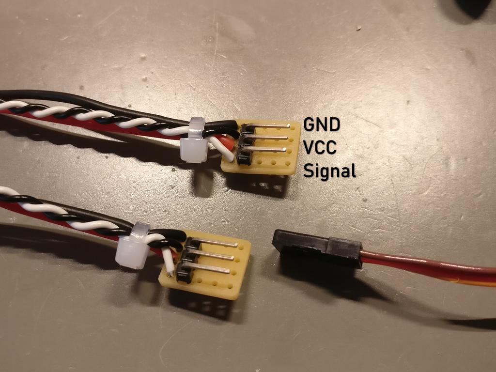
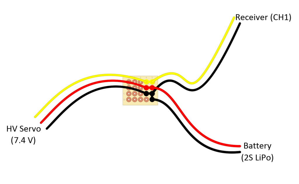
The most obvious disadvantage is, that the servo usually can’t be plugged directly into the receiver anymore. There needs to be some kind of (simple) circuit, that connects only the ground and signal wires to the receiver and the ground and power (VCC) wire to the battery. There are some adapter cables already available for that — or you can just build your own. The picture below shows such a circuit using a simple perfboard.
If the HV servo is limited to, for example, 7.4 V nominal voltage (2S LiPo battery voltage range) you can’t just plug in a 3S or even 4S battery anymore. In this case the servo needs to be powered by the or a BEC, since the battery voltage is simply to high and would damage the servo.
Also: As soon as the battery is plugged in, the servo is powered. This may or may not be a problem, depending on the power consumption of the servo when idle. For the HV servos that I’m using, that doesn’t seems to be an issue, at least not for some hours or days.
Using a higher BEC voltage
Instead of connecting the HV servo directly to the battery there are two other options:
- If possible, set a higher voltage to the ESC inbuilt BEC. This requires that all devices connected, to be able to handle this higher voltage. Usually this is the receiver itself, maybe additional servos or lighting LEDs connected to the receiver.
- Connect an external or auxiliar BEC to the battery. This BEC will be dedicated to power the HV servo. In this case the BEC needs to provide a matching voltage. Some are adjustable, some only deliver a fixed voltage. In any case, this voltage should match the highest input voltage of the HV servo.
Building an adapter
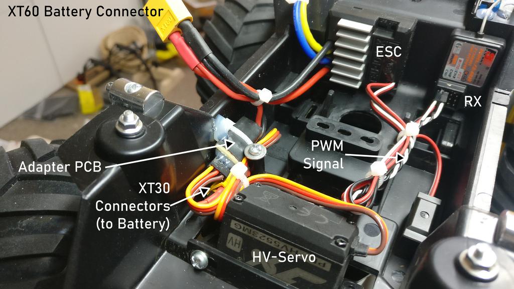
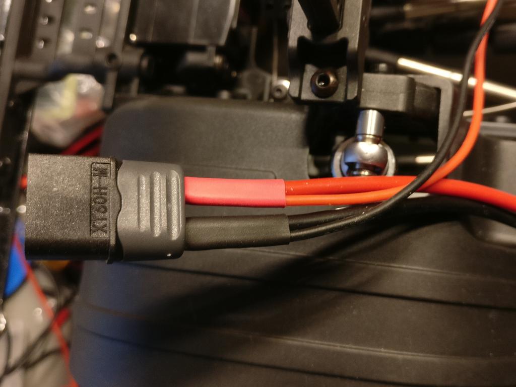
For the connection to the battery, I decided to use a female XT30-connector on the adapter. I also added a male XT30-connector in parallel to the XT60 main battery connector. The same would work, if you plan on installing an additional (external) BEC, since this also needs to be connected to the battery. Of course all this could also be soldered directly, without using additional plugs. But I think this setup adds a lot more flexibility.
The “circuit” to split the signal and power line into two separate connectors is very simple. The HV servo is plugged into a header (or soldered directly). While the white (or yellow) PWM signal wire will still be connected to the receiver (using the same type of plug), only the red power wire will now be connected directly to the main battery or auxiliar BEC. Note, that both connections/plugs also get a black ground wire, this is also called “common ground” and necessary for the circuit to work!
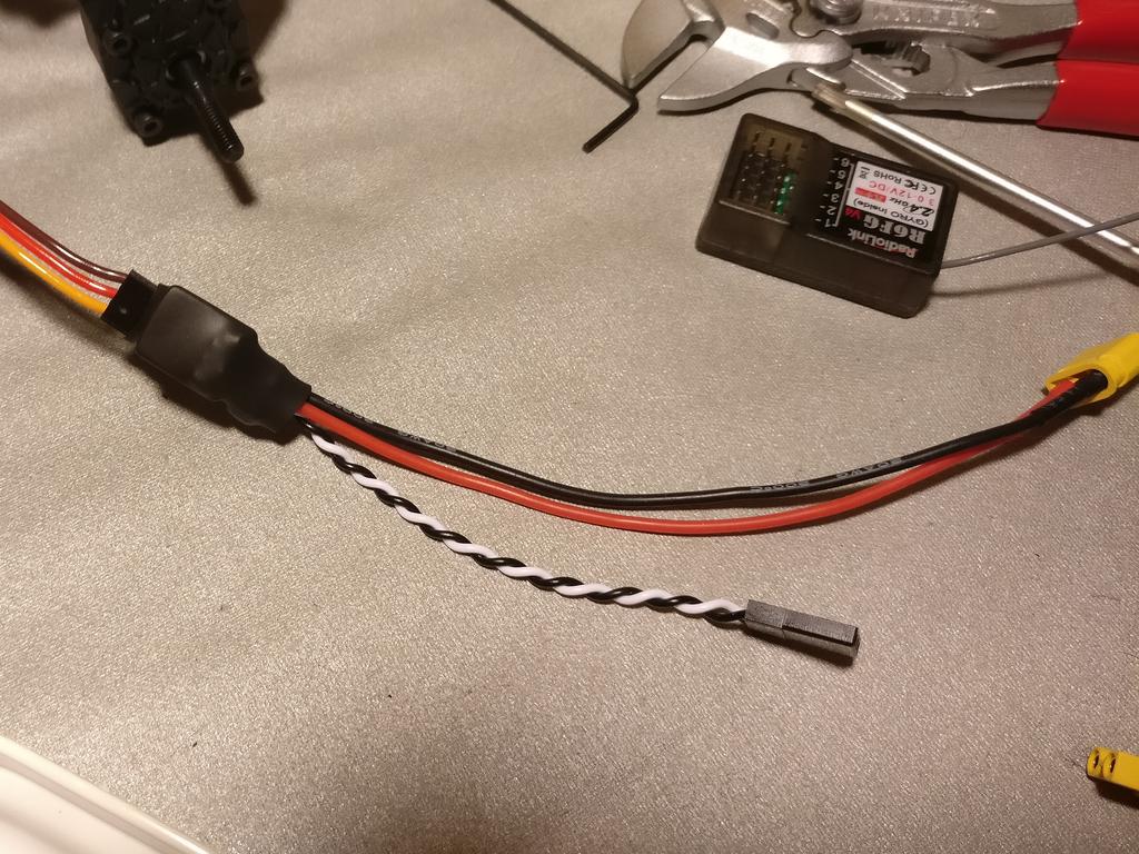
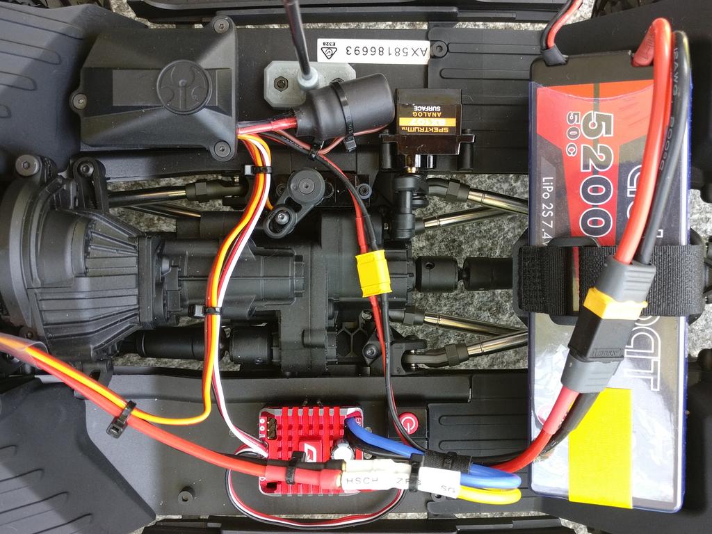
Bellow are some pictures of two identical adapters I made. In this case the yellow XT30 is supposed to be connected to the battery, the white/black wire to the receiver and the servo itself is plugged into the header. This way the servo can easily be replaced or its power source changed — for example for troubleshooting purposes.

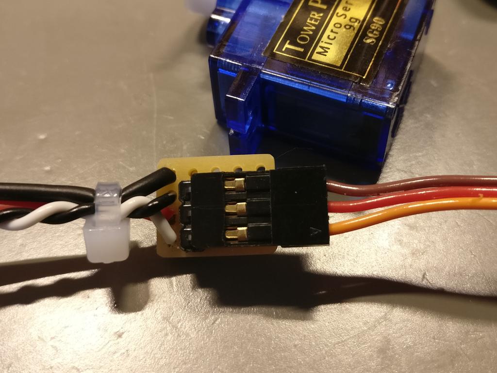
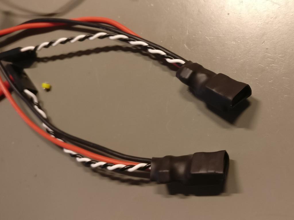
Ready built adapter. Two adapters, each with a header to connect a servo to. (Test) servo connected to the adapter. Backside of the adapters. I used some heat-shrink tubing to protect and insulate the PCBs.