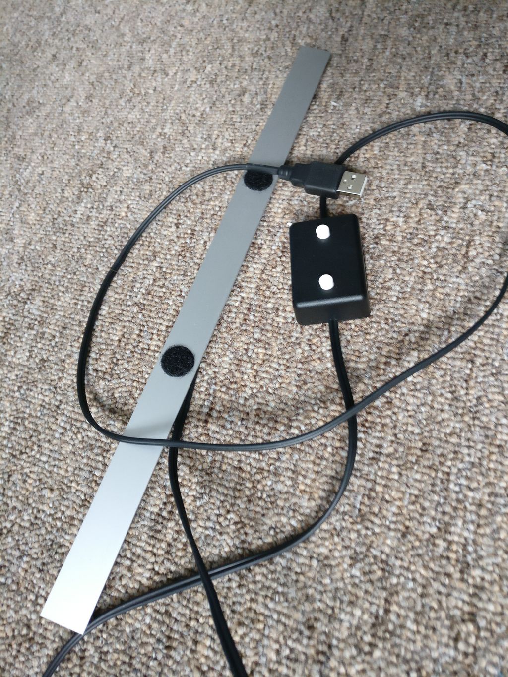
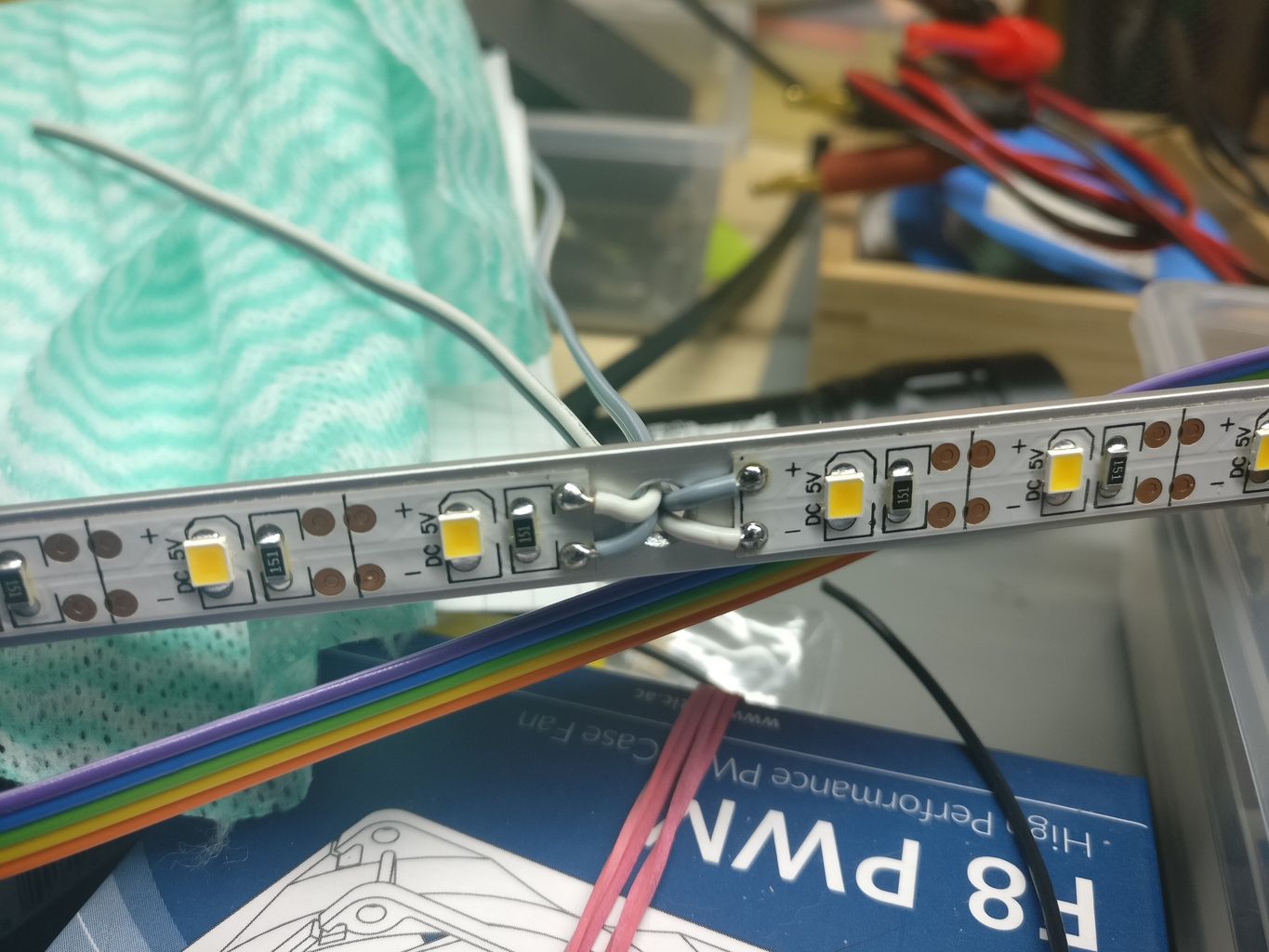
Some time ago, I decided to build simple but decent LED stripes, to put them under my PC’s displays and illuminate the keyboard and the working space directly beneath. I used 5 V LED strips, since plugging the light into a free USB port, seemed to the be easiest way to power the light.


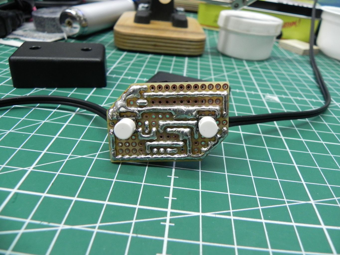
After playing around with the lights, I found them way too bright at full USB voltage. At first, I thought about using a power resistor (or multiple resistors) to reduce the current flowing through the LEDs. But I couldn’t really decide which brightness seemed to be right for me – so I decided to use PWM to dim the light down and make it adjustable at the same time. For this, I used a small black plastic case for the circuitry and the buttons.
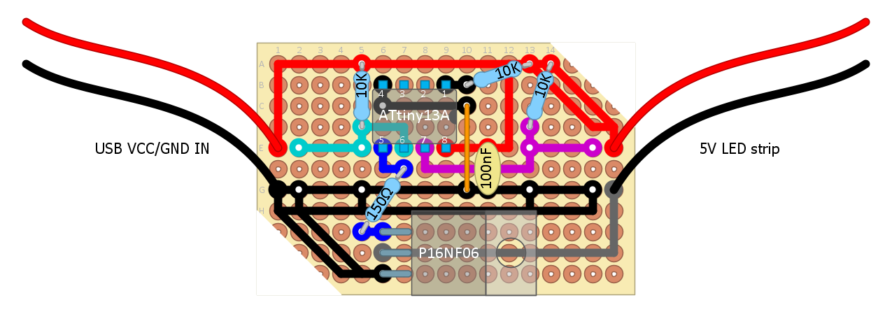
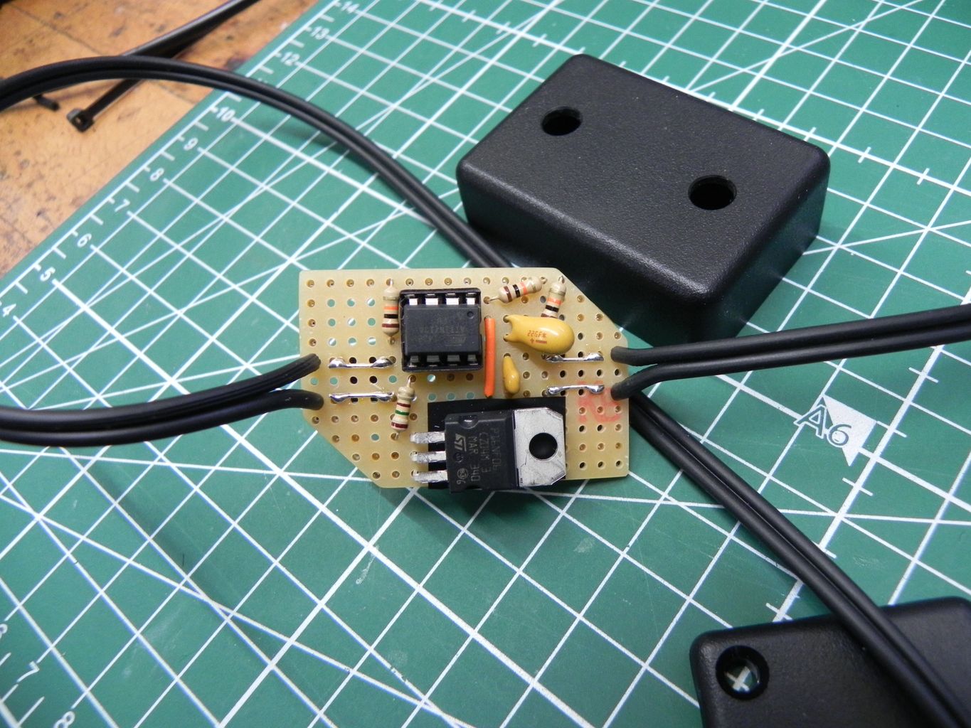
The “smallest” and most likely cheapest micro-controller I had available, was the ATtiny13a. The controller supports hardware based PWM, works with 5 V or even less voltage and has enough pins to additionally connect two buttons for dimming up and down the light.
For programming the micro-controller, I used the bare avr-libc with the avr-gcc compiler. The program uses the EEPROM of the micro-controller to save the brightness setting, if it hasn’t been changed for about five minutes. After the power was cut, the light will return to this brightness value. Simply pressing the buttons will dim the LED strip up or down.
#ifndef __AVR_ATtiny13A__
#define __AVR_ATtiny13A__
#endif

#include <avr/io.h>
#include <avr/interrupt.h>
#include <avr/eeprom.h>
//#include <util/delay.h>

#define PB0_PWM_LED PB0
#define PB3_BUTTON_DOWN PB1
#define PB4_BUTTON_UP PB2

#define PINB0_PWM_LED PINB0
#define PINB3_BUTTON_DOWN PINB1
#define PINB4_BUTTON_UP PINB2

#define DDB0_PWM_LED DDB0
#define DDB3_BUTTON_DOWN DDB1
#define DDB4_BUTTON_UP DDB2

/*
 * MCU: ATtiny13A
 *
 * Pin 1 - Reset
 * Pin 2 - [PB3]
 * Pin 3 - [PB4]
 * Pin 4 - GND
 * Pin 5 - [PB0] PWM LED (to MOSFET Gate)
 * Pin 6 - [PB1] Button 1 (DOWN)
 * Pin 7 - [PB2] Button 2 (UP)
 * Pin 8 - VCC
*/

const uint8_t PWM_BOTTOM = 0;
const uint8_t PWM_TOP = 255;
uint8_t* PWM_EEPROM_ADDRESS = (uint8_t*) 0x00;

uint16_t volatile to_counter = 0;  // Counter for timer overflows
uint16_t loop_counter = 0;  // Counter for loops in main()

uint8_t debounceDown = 0;
uint8_t debounceUp = 0;

// Timer Overflow Interrupt ISR
// Calling the ISR resets the TOV0 flag in the TIFR register.
ISR(TIM0_OVF_vect) {
  to_counter++;
}

void setupPWM(void) {
  // Set to inverted Fast PWM Mode (TOP = 0xFF)
  // Inverted because this allows switching off light completely
  // OCR0A is equivalent to (255 - duty cycle)
  TCCR0A |= (1 << COM0A1) | (1 << COM0A0) | (1 << WGM01) | (1 << WGM00);

  // Init counter
  OCR0A = PWM_TOP;  // Duty cycle

  // Formula for Fast PWM frequency: F_CPU / (Prescaler * 256)
  // 9,6 MHz: 9.600.000 / (8 * 256) = 4687,5 ==> ~4,7 kHz
  // 9,6 MHz: 9.600.000 / (64 * 256) = 585,9375 ==> ~586 Hz

  // Set prescaler to 64
  TCCR0B |= (0 << WGM02) | (0 << CS02) | (1 << CS01) | (1 << CS00);

  // Enable Timer Overflow Interrupt
  TIMSK0 |= (1 << TOIE0);
}

void delay_overflows(uint16_t overflows) {
  uint8_t sreg_before = SREG;  // Save global interrupt state
  cli();
  uint16_t to_counter_before = to_counter;  // Save counter value
  to_counter = 0;
  sei();
  while (to_counter < overflows) {}  // Wait...
  cli();
  to_counter = to_counter_before;  // Reset counter to previous value
  SREG = sreg_before;  // Restore global interrupt state
}

int main(void) {
  DDRB |= (1 << DDB0_PWM_LED);
  // Buttons have external 10k pull-up resistors!
  //PINB |= (1 << PINB3_BUTTON_DOWN) | (1 << PINB4_BUTTON_UP);

  setupPWM();

  // Read saved PWM value from EEPROM and
  // fade light up until the saved value is reached.
  while (OCR0A > eeprom_read_byte(PWM_EEPROM_ADDRESS)) {
    OCR0A--;
    delay_overflows(59); // Wait about 100 ms
  }

  sei();

  while (1) {
    if (to_counter > 10) {  // about 10 ms

      cli();

      if (~PINB & (1 << PINB3_BUTTON_DOWN)) {
        if (debounceDown++ > 4) {
          if (OCR0A < PWM_TOP) {
            OCR0A++;  // Inverted PWM mode! + ==> less
            loop_counter = 0;
          }
          debounceDown = 0;
        }
      } else {
        if (debounceDown > 0) {
          debounceDown--;
        }
      }

      if (~PINB & (1 << PINB4_BUTTON_UP)) {
        if (debounceUp++ > 4) {
          if (OCR0A > PWM_BOTTOM) {
            OCR0A--;  // Inverted PWM mode! - ==> more
            loop_counter = 0;
          }
          debounceUp = 0;
        }
      } else {
        if (debounceUp > 0) {
          debounceUp--;
        }
      }

      // Save current PWM setting to EEPROM (if different)
      if (loop_counter++ > ((uint16_t) 30 * 1000)) {  // About 5 minutes
        if (OCR0A != eeprom_read_byte(PWM_EEPROM_ADDRESS)) {
          eeprom_update_byte(PWM_EEPROM_ADDRESS, OCR0A);
          // Give some visual feedback
          uint8_t pwm_before = OCR0A;
          OCR0A = PWM_TOP; // Turn off
          delay_overflows(117);  // Wait about 200 ms
          OCR0A = pwm_before;
        }
        loop_counter = 0;
      }

      to_counter = 0;
      sei();
    }
  }
}